Woohoo: VST takes the next step
- kyle Hailey
- Jul 8, 2011
- 4 min read
Updated: Dec 9, 2024
The new release of DB Optimizer , version 3.0, from Embarcadero has awesome new feature : explain plan overlay onto VST diagrams!
Let’s take an example query:
SELECT COUNT (*)
FROM   a,
       b,
       c
WHERE
       b.val2 = 100 AND
       a.val1 = b.id AND
       b.val1 = c.id;
There are indexes on b.id and c.id. Diagramming the query in DB Optimizer gives

The red lines with crows feet mean that as far as the definitions go, the relations could be many to many.
Question is “what is the optimal execution path for this query?”
One of the best execution plans is to
start at the most selective filter table
join to parent if possible (joining to the parent will keep the runinng row set the same or potentially smaller)
else join to children (we wait to join to the children, i.e. the larger table until the last minite to delay increasing the running row set of rows returned)
There is one filter in the diagram, represented by the green F on table B. Table B has a filter criteria in the query “b.val2=100”.
Ok, table B is where we start the query. Now where do we go from B? Who is the parent and who is the child? It’s not defined in the constraints nor indexes on these tables so it’s hard for us to know. Guess what ? It’s also hard for Oracle to figure it out. Well, what does Oracle decide to do? This is where the cool part of DB Optimizer 3.0 comes in.
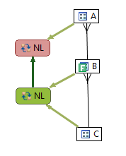
The super cool thing with DB Optimizer 3.0 is we can overlay the diagram with the actual execution path (I think this is so awesome)

For the digram we can see Oracle starts (green node) with B and joins to A. The result if this is joined to C (red node, the end of joining).
Is this the optimal path?
Well, let’s keep the same indexes and just add some constraints: ( I created the data set such that there was a parent child, i.e primiary key foreign key relationship in the data, it just wasn't explicity declared in any constraints. The indexes were already in place but there was no unique constraint on the indexes. We can add the unique constraint to the indexes and there is no extra work as the data was already unique)
alter table c add constraint c_pk_con unique (id);
alter table b add constraint b_pk_con unique (id);
Now let’s diagram the query with DB Optimizer:

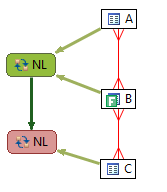
We can now see who the parent and child is, so we can determine the optimal query path which is to start at B, the only filter and join to the child C then to the parent A. Now what does Oracle do with the added constraint info:

Guess what? The execution plan has now changed with the addition of constraints and now Oracle’s execution path goes from a suboptimal plan to the optimal path. Moral of the story is to make sure and define constraint information because it helps the optimizer, but what I wanted to show here was the explain plan overlay on the diagram which makes comparing execution plans much easier. Putting the queries VST diagrams side by side along with the overlay of execution path we can clearly and quickly see the differences:
In summary, the best execution plan is to start at the most selective predicate filter and then join to the parent and finally the children. In the above example, there is only one predicate filter on B. Starting B we didn't know where to go , either to A or C because originally there were no constraints on A or C that would help us determine which was the child and which was the parent ( even though there were indexes in on these tables). Without the unique constraints on the existing indexes, Oracle got the execution plan wrong and started with the child, table A, instead of the parent C. Once we declared constraints, i.e. changing the indexes to unique indexes, then Oracle knew which was the parent and which was the child and then join first to the parent (less rows) and lastly to the child (which generally increases the rows returned).
Here is an example from an article by Jonathan Lewis
The query Jonathan discusses is
SELECT order_line_data
FROM
         customers cus
         INNER JOIN
         orders ord
         ON ord.id_customer = cus.id
         INNER JOIN
         order_lines orl
         ON orl.id_order = ord.id
         INNER JOIN
         products prd1
         ON prd1.id = orl.id_product
         INNER JOIN
         suppliers sup1
         ON sup1.id = prd1.id_supplier
   WHERE
         cus.location = 'LONDON' AND
         ord.date_placed BETWEEN '04-JUN-10' AND '11-JUN-10' AND
         sup1.location = 'LEEDS' AND
    EXISTS (SELECT NULL
            FROM
                 alternatives alt
                 INNER JOIN
                 products prd2
                 ON prd2.id = alt.id_product_sub
                 INNER JOIN
                 suppliers sup2
                 ON sup2.id = prd2.id_supplier
           WHERE
                  alt.id_product = prd1.id AND
                  sup2.location != 'LEEDS')
which diagrammed looks like

There are multiple filters, so we need to know which one is the most selective to know where to start, so we ask DB Optimizer to display the statistics as well (blue below a table is the filter %, green above is # of rows in table and numbers on join lines are rows returned by a join of just those two tables)

Now that we can determine a candidate for best optimization path, does Oracle take it?

Can you find the optimization error?
Dark green is where execution starts. There are two starts: one for the main query body and one for the subquery.
The red is where query execution ends.
For the most part Oracle gets the execution path correct. Oracle starts at CUSTOMERS (on the bottom left). Customers has the most selectve predicate filter at 0.5%. The only mistake Oracle makes is in the subquery. Oracle starts the subquery by joining ALTERNATIVES and PRODUCTS neither of which have a predicate filter. But SUPPLIERS has a preficate filter which filters out about half the rows (50.51%). Its not a huge gain but it does improve the overall performance to start the subquery on SUPPLIERS and PRODUCTS instead of ALTERNATIVES and PRODUCTS .
This kind of optimization would be extremely tedious for me to find normally but with the VST diagram and the predicate filter ratios its pretty easy.


Comments